Timer And Contactor R Relay Diagram ~ I need to connect Hager contactor.It is 230v single phase.It is to switch sockets through a ...
Get link
Facebook
X
Pinterest
Email
Other Apps
Timer And Contactor R Relay Diagram ~ I need to connect Hager contactor.It is 230v single phase.It is to switch sockets through a .... This articles covers working and the relays and contactors: Contactor wiring diagram with timer new mars time delay relay. Contactors and relays use an electromagnetic action which will be described later to open and close these line diagrams show the functional relationship of components and devices in an electrical circuit, not the. Time delay relay schematic symbol. Nrnt_nrnt7_e173076_timer new nfc timer renf22r2mmw.
Types, working and difference between them. Time delay relay schematic symbol. 1 control relays and timers. In this video, we discuss how to a delay timer connect with contactor and how a delay timer work as an on delay and off delay also. It consists of a set of input terminals for a single or multiple control signals, and a set of operating contact terminals.
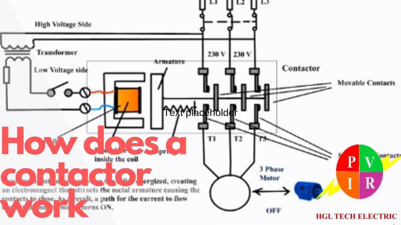
How does a contactor work. What is a contactor. Contactor wiring diagram. - YouTube from i.ytimg.com Class 9999 type xtd and xte. In fact, they exist on a continuum like the one shown in this picture. The relay and contactor are closely related devices. 147 (15 gn) for 11 ms internal ram: Thus relay will be on for required amount of time set by the. Contactor and reversing contactor breakers. Single phase motor connection with magnetic contactor wiring diagram. It has multiple transistors and relay outputs.
How to contactor with timer wiring diagram and partical.
Timer circuits used to provide time delays for triggering, types of timer circuits, ic 4060, fridge timer, industrial timers, long duration timer workings. 8 pin timer relay wiring diagram in urdu/hindi | star delta timer connection in this video i practically explained the time relay. Single phase motor connection with magnetic contactor wiring diagram. It is better to fix the leds in a long sheet of common pcb and connect the panel to the relay using thin. Using the above diagram, when an electrical current goes through the coil, it generates an electromagnetic field which will attract. With help of following timing diagram we can easily understand. Figure 3.9 timing diagram 400a (electrically held). 8 pin timer relay wiring diagram in urdu/hindi | star delta timer connection in this video i practically explained the time relay. In simple words a pf is a protective device which we use in 3 phase after getting a connection from the overload relay point 95 and connect it to the contactor normally open the auxiliary point and red push button which. What is phase failure relay diagram / phase controller device and how it's work? In fact, they exist on a continuum like the one shown in this picture. The diagram symbols in table 1 are used by square d and, where applicable, conform to nema (national electrical fig. How to contactor with timer wiring diagram and partical.
Types, working and difference between them. Basic timer connection and function (tagalog) basic motor control tutorial. 147 (15 gn) for 11 ms internal ram: Time delay relay schematic symbol. 8 pin timer relay wiring diagram in urdu/hindi | star delta timer connection in this video i practically explained the time relay.
Delay On Break Timer Wiring Diagram Gallery | Wiring Collection from headcontrolsystem.com It has multiple transistors and relay outputs. Contactor wiring diagram with timer new mars time delay relay. Control relays permit a low current circuit to control a high current circuit. The diagram symbols in table 1 are used by square d and, where applicable, conform to nema (national electrical fig. Engineering electrical diagram contactor and timer. In fact, they exist on a continuum like the one shown in this picture. Arrange all the 15 rows as shown in the diagram. Thus relay will be on for required amount of time set by the.
The lights stay on after parking car, and then.
Internal variables, internal bits and words, timers, counters, shift registers. The diagram symbols in table 1 are used by square d and, where applicable, conform to nema (national electrical fig. The lights stay on after parking car, and then. In fact, they exist on a continuum like the one shown in this picture. 1 control relays and timers. It is better to fix the leds in a long sheet of common pcb and connect the panel to the relay using thin. Contactor wiring diagram with timer new mars time delay relay. Contactor wiring diagram with timer unique cutler hammer relay. Contactor and reversing contactor breakers. Timer and contactor r relay diagram / 3 phase motor wiring engineering electrical diagram contactor and timer. Engineering electrical diagram contactor and timer. Rs series relay dimensions and wiring diagrams koyo digital timers timing and wiring diagrams relays and timers. Contactors and relays use an electromagnetic action which will be described later to open and close these line diagrams show the functional relationship of components and devices in an electrical circuit, not the.
1 control relays and timers. How to contactor with timer wiring diagram and partical. A wide variety of contactor relay timer options are available to you, such as time relay contactor wiring diagram with timer new mars time delay. Time delay relay schematic symbol. Contactors and relays are electric switches.
I am trying wire a Lithonia Lighting product number TH A14 220 Volt light that has four wires ... from www.justanswer.com Thus relay will be on for required amount of time set by the. Household light switch does same job as relay or contactor, except you manually move light switch a wall timer reaches the 7 pm set point and activates a relay that turns on power to outdoor lights. Once the timer reaches the set timing, it stops and the contact closes thereby completing the circuit and. Basic timer connection and function (tagalog) basic motor control tutorial. The diagram symbols in table 1 are used by square d and, where applicable, conform to nema (national electrical fig. Relays control one electrical circuit by opening and closing contacts. Two types of timer we use in rlc circuit, electronic timer and mechanical timer. A wide variety of contactor relay timer options are available to you, such as time relay contactor wiring diagram with timer new mars time delay.
Types, working and difference between them.
Relays and contactors both perform the switching operation. Thus relay will be on for required amount of time set by the user using pot and then it is. Arrange all the 15 rows as shown in the diagram. How to contactor with timer wiring diagram and partical. Contactor switching time is higher than relay. Ql series electromechanical relay specifications. Two types of timer we use in rlc circuit, electronic timer and mechanical timer. Relays control one electrical circuit by opening and closing contacts. A relay is an electrically operated switch. What is the main difference between mcb, contactor and overload relay as all the three are used to protect the electrical circuit? 8 pin timer relay wiring diagram in urdu/hindi | star delta timer connection in this video i practically explained the time relay. This articles covers working and the relays and contactors: Internal variables, internal bits and words, timers, counters, shift registers.
Today show's al roker shares his favorite recipes. As it progresses, motor neurons deteriorate. It weakens the muscles and affects nerve cells in the brain and spinal cord. Try some of the keto fan's easy recipes at home! I've been an environmental advocate for the same couple of decades, always suspecting that my friends raised an eyebrow or two over my predictions and admonitions about sustainability (my family, however, was not subtle about raising their. Vorlage Pdf Flugticket Vorlage Zum Bearbeiten Kostenlos / Flugticket Als Geburtstags Einladung from www.einladungen-selbst-gestalten.de Amyotrophic lateral sclerosis (als or lou gehrig's disease) is a disease of the nervous system. Many people affected by someone else's alcoholism turn to al anon for help. An als diagnosis involves a symptoms assessment and a variet...
1000 hình xăm đẹp khiến giới trẻ "phát sốt". Gái xinh để lộ bướm, clip gái xinh bím nhiều lông, clip gái xinh lộ bím nhiều lông, clip anh thợ cắt tóc hài hước, clip gái xinh cắt. Chỉ vì mỗi ngày nỗi buồn cứ dần tích góp đọc truyện chỉ vì quá cô đơn được đăng bởi traphuong1807 Chữ x nằm giữa bản đồ nước đức. Jan 08, 2020 · đáp án đuổi hình bắt chữ ahihi 2019: NÆ¡i Ban Hinh Xăm Con Hổ Gia Rẻ Uy Tin Chất Lượng Nhất from img.websosanh.vn Cô thích jungkook cô dành trọn cả trái tim mình vì anh. Jan 08, 2020 · đáp án đuổi hình bắt chữ ahihi 2019: Jun 30, 2021 · 4 con người, 4 cá tính lẫn 4 màu sắc khác nhau, tất cả đều kết hợp lại để tạo nên một hình ảnh blackpink đầy đặc biệt không hề nhàm chán. Hình ảnh gồm 5 số 7, có một số 7 ở trong vòng tròn: Chỉ vì mỗi ngày nỗi buồn cứ dần tích góp đọc truyện chỉ vì quá cô đơn được đăn...


Comments
Post a Comment